Drone Tracking!
Overview
This was my (individual) Final Year Project as part of my Electronics and Information Engineering ( EIE ) degree curriculum at Imperial College London.
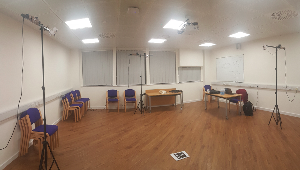
The goal of the project was to design and implement a real-time State Estimation and Navigation system ( for indoor environment ) for a Parrot A.R. Drone using cheap equipment. The main hypothesis explored in this project was: Multiple Internet Protocol ( IP ) cameras can be used for precise monitoring/tracking a Parrot A.R Drone in an indoor environment.
The project can be broadly divided into a State Estimation phase and Navigation phase. The following sections give a brief overview of each phase and also provide a video of both components in practice.
Task 1: State Estimation
The first task was to find the State/pose of the drone using LEDs placed on the drone hull.
Click on any one of the play/pause button on the videos to play/pause all of them simultaneously. The camera images are synchronized so as to combine measurements from the 3 cameras. Notice that the resolution of the (nearly) real-time video stream is low (640 x 480p). This is because the State Estimation module was too slow (high latency) when using the IP cameras at HD resolution.In order to quickly verify (visually/qualitatively) the estimation accuracy, 3D meshes were projected onto each camera image using the Projection function of the camera. Two 3D meshes (blue and pink) are projected onto the camera image. The blue mesh is projected using camera-to-drone pose, pink mesh is projected using world-to-camera pose.
Based on the video, two key observations can be made:- 1) The state estimates from each camera agree well with each other (since pink mesh almost aligns with blue mesh).
- 2) State Estimate obtained from each camera is reasonably accurate (since the blue mesh aligns well with the drone in each camera image).
Task 2: Feedback Control
After building a State Estimation module, the best way to confirm the accuracy is to integrate a closed-Loop Feedback controller with the State Estimation module.
Evaluation: Simple Navigation Test
To confirm/validate the Estimation accuracy (a single camera is used for estimation in videos below), and the Feedback Controller is integrated into the system. The destination point is marked on the ground (as a cross mark with black tape) and its coordinates are found using a standard measuring tape. These coordinates are provided to the Feedback controller and the drone is made to navigate from the starting point to the destination point.
Since wireless cameras are used in this project, they incur a latency which affects the Navigation module. Consider the example scenario shown in video (on) the left): the PID controller is provided with a desired 3D point/coordinate and the drone must be landed there on reaching near it. When the complete system is run, it is only after the drone moves past the desired point the camera(s) infer the drone to be at/above the landing point and the PID controller commands it to land incorrectly. This latency is known as end-to-end latency and is unavoidable and may only be fixed by either reducing the wireless latency or making the drone hover (instead of land) at the desired location in order to give the cameras some time to catch up to the existing position of the drone.
Click on any of the videos to start it.Conclusion
This project has successfully confirmed the Hypothesis stated at the beginning. The project provides a detailed design of various components and algorithms needed to implement the State Estimation module, with a special emphasis on making sure the real-time requirements are met at every stage of the process. It is also ensured that the design is future extensible if someone wishes to continue on this project later.
The performance of the State Estimation module, both in terms of accuracy and latency was evaluated. Based on the Evaluation results, the Estimation Error was found to be approximately 5.5351 cm for Position and 2.127 degrees for Orientation. The real-time characteristic of the final design were found to be 29 FPS (if using 1 camera), 18 FPS (if using 2 cameras), 12 FPS (if using 3 cameras). These values are not as accurate/fast as commercial products, however, this is the trade-off when working with cheaper cameras and LEDs in the visible spectrum as compared to using expensive cameras and LEDs in the Infrared (IR) spectrum.
.jpg)